Thursday, September 2, 2010

Sub netting

Subnetting
Sub-netting is a process of breaking the network into smaller units. These units can be called subnets. Each subnet is a non-physical description(ID) for a physical sub-network.

Benefits of Sub netting

• Reduce network traffic.
• Reduce the size of the routing table.
• Simplified Management: It’s easier to identify and isolate network problems in a group of smaller connected networks than within one gigantic network.
• Optimized network performance: This is a result of reduced network traffic.
• It also increases security of the network and helps contain network traffic to local network segments.

With sub-netting, the number of segments increases, while the number of hosts in each segment reduces. For example, consider a network with an IP address of 192.168. 2.0. With the default subnet mask of 255.255.255.0, you can have only one large network segment with 254 hosts. If you use some bits from the host portion, you can create two, three, or four segments. But as the number of segments increases, the number of hosts in each segment reduces.

Implementing Sub netting

Before implementation, we can determine some requirement and plans to best implement your subnet scheme.
• Determine the number of required network IDs
       -One for each subnet
       -One for each wide-area network connection.
• Determine the number of required host IDs per subnet
       -One for each TCP/IP host
       -One for each router interface
• Define one subnet mask based on requirements.
• Define a unique subnet ID for each physical segment based on the subnet mask.
• Define valid host IDs for each subnet based on the subnet ID.

Subnet Mask

Subnet mask is a 4 byte (32 bits) number used to identify the sub-network ID and the host ID from an IP address. Every class of the IP address uses the different range of the sub-network. Subnet mask allow the IP based networks to be divided into the sub network, i.e, 255.255.255.0, 255.255.170.0. Table shows the default subnet mask of class A,B, and C.

Wednesday, September 1, 2010

IP Addressing

IP Addressing
An IP address is a unique address used to identify a computer or a host on the network. This address is made up of 32-bit numbers written in dotted decimal notation in the w.x.y.z format. Each eight bits are known as an octet or a byte. A part of the IP address is known as the network address, or network ID, and the rest of it is known as the host address, or host ID. These parts are based on the class of IP addresses used on the network. All computers on a particular network must have the same number as the network address, while the host address must be unique on the entire network. A second address, the subnet mask, is used to help identify the part of the network where the host is located.

IP addresses are assigned and controlled by an organization called Internet Assigned Numbers Authority (IANA). There are two current versions of IP addressing: IPv4 and IPv6.

Example: 140.179.220.200
Binary form:
140                  179              220                 200
10001100    10110011       11011100      11001000

IP Terminology:
Bit: A bit is a one digit, either a 1 or 0.
Byte: A byte is a 7 or 8 bits. Today, we can always assumed a byte is 8 bits.
Octet: An octet; made up of 8 bits.

IPv4 addresses
IPv4 addresses are classified into classes A, B, C, D, and E. Only addresses from the classes A, B, and C are assigned to organizations and are known as class-full IP addresses. The first byte of an IP address identifies the class of IP addresses used in the network. For example, a host with an IP address of 92.137.0.10 is using a class A IP address. A host with an IP address of 192.170.200.10 is using a class C IP address. The IP addresses in the A, B, and C classes are available for public companies and can be assigned by an ISP. The class D and E addresses are reserved for special usage.

IP Address Classes
IP addresses can be categorized into different types of classes. These are:
     • Class A
     • Class B
     • Class C
     • Class D
     • Class E

(i) Class A:
Class A addresses are designed for networks with a large number of hosts. The high-order bit is set to 0. The first 8 bits (the first octet) are defined as the network ID; the last 24 bits(the last three octets) are defined as the host ID. Figure illustrates the class A address.


Range is: 1-126
Maximum number of networks: 126(27-2).
Maximum nodes per networks: 16,777,214(224-2).

(ii) Class B:
Class B addresses are designed for moderate-sized networks with a moderate number of hosts. The two high-order bits are set to 10. The first 16 bits (the first two octets) are defined as the network ID; the last 16 bits (the last two octets) are defined as the host ID. Figure illustrates the class B address.

Range is: 128-191
Maximum number of networks: 16384 (214).
Maximum nodes per network: 65534(216-2).

(iii) Class C:
Class C addresses are designed for small networks with a small number of hosts. The three high-order bits are set to 110. The first 24 bits (the first three octets) are defined as the network ID; the last 8 bits (the last three octets) are defined as the host ID. Figure illustrates the class C address.

Range is : 192-223
Maximum number of networks: 2097152(221).
Maximum nodes per network: 254(28-2).

(iv) Class D
Class D addresses are for IP multicast addresses. The four high-order bits are set to binary 1110. The next 28 bits are used for individual IP multicast addresses. The Microsoft Windows Server 2003 family supports class D addresses for IP multicast traffic.
Range is : 224-239

(v) Class E

Class E addresses are experimental addresses reserved for future use. The five high-order bits in a class E address are set to 11110. The Windows Server 2003 family does not support the use of class E addresses.
Range is : 240-255.

Table : IP Address Classes

Network Address (ID)
A network address uniquely identifies a network. All the host in a single network will have the same network address. For example, in the IP address 192.9.205.21, the network ID is 192.9.205. A router analyses only the network ID portion of an address for datagram forwarding.

Node (Host) Address/ID
A node ID uniquely identify a host in a network. Two hosts in two different networks can have the same host ID. For example, in the IP address 192.9.250.21, the host ID is 21.

Private IP Addresses
An IP address is considered private if the IP number falls within one of the IP address ranges reserved for private uses by Internet Standards groups. Private IP addresses (or unregistered IP addresses), on the other hand, are used when an organization’s computer network is private. In other words, it is not connected to the Internet or if it is, it is located behind a proxy server or a firewall. Access to private networks is usually restricted to users inside the organization. The Internet Assigned Numbers Authority (IANA) has set aside a range of IP addresses in each of A, B, and C address classes that can be used by private organizations for their internal IP addressing. These addresses are listed in Table .

Private IP addresses are typically used on local networks including home, school and business LANs, including Airport and Hotels.


Devices with private IP addresses cannot connect directly to the Internet like wise, computers outside the LAN cannot directly to device with a Private IP. But if you want to access the internet with this ip address you must have to use proxy server or NAT server.

Public IP Address
Public IP addresses (or registered IP addresses) are those addresses of those networks that are accessible from outside the organization. For example, if any host is connected to a network, it is using a public IP address. If an organization needs to connect its network to the Internet, it will need to obtain a public IP address from its Internet Service Provider. Typically, web servers, email servers, DNS servers, FTP servers, and VPN servers are connected directly to the Internet and use public IP addresses.

Broadcast Address
In computer networking, a broadcast address is a network address that allows information to be sent to all nodes on a network, rather than to a specific network host. In other word’s A special type of networking address that is reserved for sending messages to all machines on a given network segment.


Wednesday, August 25, 2010

IGRP

Interior Gateway Routing Protocol is a Cisco-proprietary distance vector routing protocol. This means that to use IGRP in your network, all your routers must be Cisco Routers. Cisco created this routing protocol to overcome the problems associated with RIP.

IGRP has a maximum hop count of 255 with the default of 100 (same as EIGRP). This enables IGRP to be used in larger networks and is not limited to smaller networks with 15 hops as in the case of RIP.

The metric used by IGRP is also different from RIP. IGRP uses a combination of path characteristics, such as bandwidth and delay by default to calculate the metric. This type of metric is called composite metric. IGRP can also be use reliability, load and maximum transmission unit (MTU).

IGRP also provides various timers such as Update timers, Invalid timers, hold-down timers, flush timers to control performance. These are explained below:
(i) Update Timers

Update timer specifies how frequently routing update messages should be sent to the neighboring routers. Its default value is 90 seconds.

(ii) Invalid Timers

Invalid timer specifies how long a router should wait before declaring a route as invalid if it doesn’t receive an update about that route. Its default value is three times the update period. That means if the update timer is 90 seconds then the value of invalid timer will be sent to 270 seconds.

(iii) Hold-down timers

Hold-down timer specifies the hold-down period. Its default value is three times the update timer period plus 10 seconds. The hold-down timer will be 270 seconds plus 10 seconds that is 280 seconds.

(iv) Flush Timers

Flush timer specifies how much time should pass before a route should be deleted from the routing table. Its default value is seven times the update times. Therefore, the value of flush timer will be set to 630 seconds.

Difference between IGRP Vs RIP


Lab Practice:


Procedure:
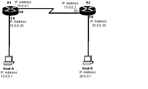
1. Configuring and Assigning the IP addresses on the Router R! and R2.
2. Check the routing table on both the routers.
3. Enable the IGRP protocol on both routers so that hosts on the both routers can communicate with each other.
4. Verifying the Routing protocols on the Router.
5. Check the routing table on both the routers after enabling the IGRP on both routers after enabling the IGRP on both sides.
6. Verifying the connection of both hosts.

Configuration:


Step1 (A): Assigning the IP addresses on the Ethernet and Serial Interfaces of Router R1 as shown in the figure.

Step1 (B): Assigning the IP addresses on the Ethernet and Serial Interfaces of Router R2 as shown in the figure.

Step2(A): Check the Routing table of the router R1.
                 R1#sh ip route

             C 10.0.0.0/8 is directly connected, Ethernet 0
             C 15.0.0.0/8 is directly connected, Serial 0

Step2 (B):Check the routing table of router R2.
                 R2#sh ip route


             C 20.0.0.0/8 is directly connected, Ethernet 0
             C 15.0.0.0/8 is directly connected, Serial 0

Step3 (A): Enable the IGRP protocol on the Router R1.
                R1(config)#router igrp 10
                R1(config-router)#network 10.0.0.0
                R1(config-router)#network 15.0.0.0

Step3 (B): Enable the IGRP on the router R2.
                R2(config)#router igrp 10
                R2(config-router)#network 20.0.0.0
                R2(config-router)#network 15.0.0.0

Step 4(A): Check the routing protocol on the router R1.
               R1#show ip protocols

Routing protocol is “IGRP 10”
Sending updates every 90 seconds, next due in 38 seconds, Invalid after 270 seconds, hold down 280 seconds, flush after 630 seconds.

IGRP metric weight K1=1, K2=0, K3=1, K4=0, K5=0

IGRP maximum hop count 100

IGRP maximum metric variance 1

Step4 (B): Check the routing protocols on the router R2.
                R2#show ip protocols

      Routing protocol is “IGRP 10”

Sending updates every 90 seconds, next due in 38 seconds, Invalid after 270 seconds, hold down 280 seconds, flush after 630 seconds.

IGRP metric weight K1=1, K2=0, K3=1, K4=0, K5=0

IGRP maximum hop count 100

IGRP maximum metric variance 1

Step5 (A): Check the Routing table after enabling the IGRP on router R1.
                 R1#sh ip route
         I 20.0.0.0/8[100/8576]via 15.0.0.2, 00:01:09, serial 0
        C 10.0.0.0/8 is directly connected, Ethernet 0
        C 15.0.0.0/8 is directly connected, Serial 0

Step5 (B): Check the Routing table after enabling the IGRP on router R2.
                 R2#sh ip route
          I 10.0.0.0/8[100/8576]via 15.0.0.1, 00:01:09, serial 0
         C 20.0.0.0/8 is directly connected, Ethernet 0
         C 15.0.0.0/8 is directly connected, Serial 0

Step 6: Verifying the connection of Host ‘A’ & Host ‘B’

C:\> ping 20.0.0.1

Monday, August 9, 2010

Routing Information Protocol (RIP)

RIP is an Open Standard Protocol based on a version that was developed at the University of California at Berkeley and was officially defined in June 1988 under Request for Comment (RFC) 1058. RIP is relatively simple distance routing protocol categorized under the family if IGP’s meaning that it performs routing within a single Autonomous System.

RIP uses hop counts as its metric to calculate the distance between the source and the destination network. Each router in a RIP network is counted as one hop. RIP implements a maximum hop count of 15. This means that a packet will never pass through more than 15 routers, because it will be discarded by the sixteenth. By using a maximum hop count, a packet will never be used in an environment that has 2 segments separated by more than 15 routers.

RIP operates by automatically sending routing updates every 30 seconds and whenever the routing table changes. A RIP update contains an entire copy of the router’s routing table. When a router receives a routing update it updates its routing table to reflect the changes.

RIP works well in small networks, but it is inefficient on large networks with slow WAN links or on networks with a large numbers of routers installed.

RIP Timers


• Routing update timer
The routing update timer is defined as the time between which routing table updates are sent to neighboring routers. A RIP routing table update sends a copy of the entire routing table to its neighbors and not just the table changes. The routing update timer is set to happen every 30 seconds.

• Route timeout timer
The router maintains a timeout timer for each entry in the routing table, which is 90 seconds by default. If a router has an entry for a particular destination network and it has not received an update about this network in a specified amount of time, the router will assume that this route has become invalid. When this expires, the router will send an update to its neighbors letting them know that this route has timed out.

• Route flush timer
After a route for a destination network is timed out from the routing table it is not removed from the routing table immediately. Instead the router waits till the flush timer (its default value is 240 seconds), which is the amount of time between when a route has become invalid and the time it’s actually removed from the routing table.