Interior Gateway Routing Protocol is a Cisco-proprietary distance vector routing protocol. This means that to use IGRP in your network, all your routers must be Cisco Routers. Cisco created this routing protocol to overcome the problems associated with RIP.
IGRP has a maximum hop count of 255 with the default of 100 (same as EIGRP). This enables IGRP to be used in larger networks and is not limited to smaller networks with 15 hops as in the case of RIP.
The metric used by IGRP is also different from RIP. IGRP uses a combination of path characteristics, such as bandwidth and delay by default to calculate the metric. This type of metric is called composite metric. IGRP can also be use reliability, load and maximum transmission unit (MTU).
IGRP also provides various timers such as Update timers, Invalid timers, hold-down timers, flush timers to control performance. These are explained below:
(i) Update TimersUpdate timer specifies how frequently routing update messages should be sent to the neighboring routers. Its default value is 90 seconds.
(ii) Invalid Timers
Invalid timer specifies how long a router should wait before declaring a route as invalid if it doesn’t receive an update about that route. Its default value is three times the update period. That means if the update timer is 90 seconds then the value of invalid timer will be sent to 270 seconds.
(iii) Hold-down timers
Hold-down timer specifies the hold-down period. Its default value is three times the update timer period plus 10 seconds. The hold-down timer will be 270 seconds plus 10 seconds that is 280 seconds.
(iv) Flush Timers
Flush timer specifies how much time should pass before a route should be deleted from the routing table. Its default value is seven times the update times. Therefore, the value of flush timer will be set to 630 seconds.
Difference between IGRP Vs RIP
Lab Practice:
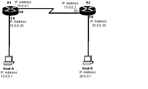
1. Configuring and Assigning the IP addresses on the Router R! and R2.
2. Check the routing table on both the routers.
3. Enable the IGRP protocol on both routers so that hosts on the both routers can communicate with each other.
4. Verifying the Routing protocols on the Router.
5. Check the routing table on both the routers after enabling the IGRP on both routers after enabling the IGRP on both sides.
6. Verifying the connection of both hosts.
Configuration:
Step1 (A): Assigning the IP addresses on the Ethernet and Serial Interfaces of Router R1 as shown in the figure.
Step1 (B): Assigning the IP addresses on the Ethernet and Serial Interfaces of Router R2 as shown in the figure.
Step2(A): Check the Routing table of the router R1.
R1#sh ip route
C 10.0.0.0/8 is directly connected, Ethernet 0
C 15.0.0.0/8 is directly connected, Serial 0
Step2 (B):Check the routing table of router R2.
R2#sh ip route
C 20.0.0.0/8 is directly connected, Ethernet 0
C 15.0.0.0/8 is directly connected, Serial 0
Step3 (A): Enable the IGRP protocol on the Router R1.
R1(config)#router igrp 10
R1(config-router)#network 10.0.0.0
R1(config-router)#network 15.0.0.0
Step3 (B): Enable the IGRP on the router R2.
R2(config)#router igrp 10
R2(config-router)#network 20.0.0.0
R2(config-router)#network 15.0.0.0
Step 4(A): Check the routing protocol on the router R1.
R1#show ip protocols
Routing protocol is “IGRP 10”
Sending updates every 90 seconds, next due in 38 seconds, Invalid after 270 seconds, hold down 280 seconds, flush after 630 seconds.
IGRP metric weight K1=1, K2=0, K3=1, K4=0, K5=0
IGRP maximum hop count 100
IGRP maximum metric variance 1
Step4 (B): Check the routing protocols on the router R2.
R2#show ip protocols
Routing protocol is “IGRP 10”
Sending updates every 90 seconds, next due in 38 seconds, Invalid after 270 seconds, hold down 280 seconds, flush after 630 seconds.
IGRP metric weight K1=1, K2=0, K3=1, K4=0, K5=0
IGRP maximum hop count 100
IGRP maximum metric variance 1
Step5 (A): Check the Routing table after enabling the IGRP on router R1.
R1#sh ip route
I 20.0.0.0/8[100/8576]via 15.0.0.2, 00:01:09, serial 0
C 10.0.0.0/8 is directly connected, Ethernet 0
C 15.0.0.0/8 is directly connected, Serial 0
Step5 (B): Check the Routing table after enabling the IGRP on router R2.
R2#sh ip route
I 10.0.0.0/8[100/8576]via 15.0.0.1, 00:01:09, serial 0
C 20.0.0.0/8 is directly connected, Ethernet 0
C 15.0.0.0/8 is directly connected, Serial 0
Step 6: Verifying the connection of Host ‘A’ & Host ‘B’
C:\> ping 20.0.0.1

